
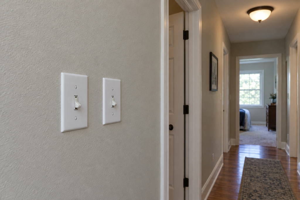
A 3-way switch pair lets you control one light from two locations, and the whole job comes down to one rule: the always-hot feed lands on the common terminal of the first switch, the wire to the light lands on the common of the second, and the two travelers connect brass screw to brass screw between them. Get those three connections right and the light works from either end. Here is how to do it with 14/3 cable, plus the diagrams for the three layouts you will actually meet in a house.
Quick steps: wire a 3-way switch
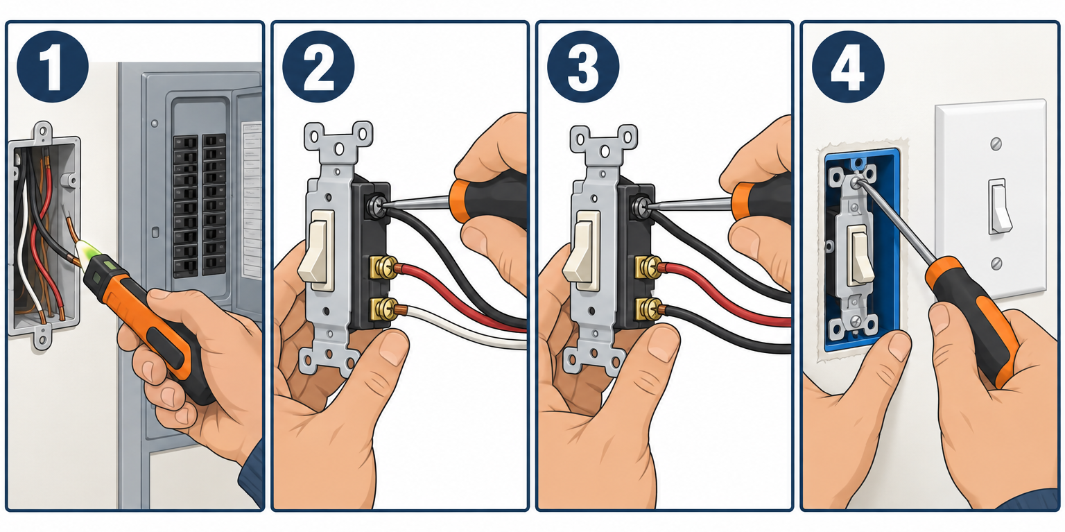
- Turn off the breaker and test every wire in both boxes with the other switch in both positions.
- Run 14/3 NM-B (15 A circuit) or 12/3 (20 A) between the two switch boxes.
- At switch 1, feed black to the common (dark screw), red and black of the 3-wire to the brass travelers.
- Splice the whites straight through and pigtail all grounds to the green screw.
- At switch 2, red and black travelers to brass, the black going to the light on the common.
- Wire the fixture black to black, white to white, ground to ground.
- Fold conductors in, mount the switches, restore power and test from both ends.
Tools and materials
- Two 3-way switches, 15 A (toggle $3-6, Decora-style $6-12 each)
- 14/3 NM-B cable with ground (about $1.20-1.60 per foot), or 12/3 on a 20 A circuit
- 14/2 NM-B for the feed and the leg to the light
- Wire connectors (yellow for 2-3 #14 conductors, red for 4-5)
- Non-contact voltage tester and a multimeter
- Wire stripper, lineman’s pliers, #2 Phillips and flat screwdrivers
- Black electrical tape, 6-inch green ground pigtails
- 18 cu in single-gang boxes if you are adding new ones
- Cable staples and a drywall saw for new runs
Safety first
Switch off the breaker, then test every conductor in both boxes with a non-contact tester while a helper flips the other switch to each position. A 3-way circuit can put voltage on either traveler depending on switch position, so one quick test is not enough.
What the terminals on a 3-way switch do
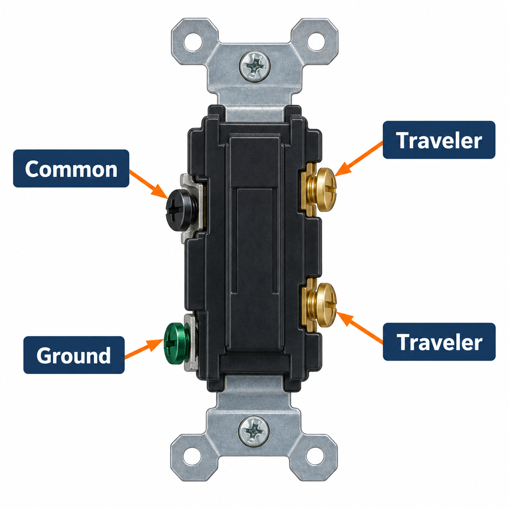
Flip a 3-way switch over and you will see four screws. The one dark or black screw is the common. The two brass screws are the travelers. The green screw is ground. There is no ON or OFF printed on the toggle because up and down mean nothing until you know the position of the other switch.
Inside, the switch is a single-pole double-throw contact. It connects the common to one traveler or the other, never both. With two switches wired traveler to traveler, flipping either one completes or breaks the path. That is all a three way switch does, and every diagram below is just a different route for the same three connections.
3-way switch wiring diagram: the 3 layouts you will find
Diagram A is what you should build for new work. B and C show up in older houses and are fine to repair like for like, but both leave at least one switch box without a neutral, which NEC 404.2(C) has required at most switch locations since the 2011 edition. If you are pulling new cable, pick A.
Diagram A: Power at switch 1, light after switch 2 (recommended)
PANEL ──14/2──► [SW1] ──14/3──► [SW2] ──14/2──► LIGHT

SW1 box: feed black ─► COMMON (dark screw)
         14/3 red  ─► brass traveler
         14/3 black─► brass traveler
         feed white ═ 14/3 white (spliced, passes through)
         grounds pigtailed to green screw

SW2 box: 14/3 red  ─► brass traveler
         14/3 black─► brass traveler
         light black ─► COMMON
         14/3 white ═ light white (spliced)
Diagram B: Power at the light first (older switch loop)
PANEL ──14/2──► LIGHT ──14/3──► [SW1] ──14/3──► [SW2]

Light box: feed black ═ 14/3 white (tape it black, this is now hot)
           feed white ─► fixture white
           14/3 black ─► fixture black (switched return)
SW1 box:   taped white ─► COMMON
           red and black to SW2 ─► brass travelers
           white from SW2 (taped black) ═ black back to light
SW2 box:   red and black ─► brass travelers
           taped white ─► COMMON
Diagram C: Light between the switches
PANEL ──14/2──► [SW1] ──14/3──► LIGHT ──14/3──► [SW2]

SW1 box:   feed black ─► COMMON; red and black ─► travelers; whites spliced
Light box: red ═ red, black ═ black (travelers pass through)
           white from SW1 ─► fixture white
           white from SW2 (taped black) ─► fixture black
SW2 box:   red and black ─► travelers; taped white ─► COMMON
Any time a white wire carries current as a hot or switched hot, wrap black tape on it at both ends. Inspectors look for it, and the next person in the box will thank you.
Step 1: Kill the power and identify the common
Turn off the breaker and verify with the tester as described above. If you are replacing existing switches, photograph each one before touching a wire, then put a piece of tape on the conductor attached to the dark common screw. Mixing up a traveler with the common is the number one cause of a pair that “half works.”
Pro tip
Not sure which box has the feed? With the breaker on, one wire in the two boxes reads 120 V to ground no matter how you flip the switches, while the travelers alternate between hot and dead as you flip. The wire that stays hot in every position is your feed, and it goes on the common of that switch. Then shut the breaker back off before you start.
Step 2: Run the 3-wire cable
Between the two switch boxes you need three insulated conductors plus ground, so 14/3 NM-B on a 15 A breaker or 12/3 on a 20 A breaker. Match the existing wire gauge; 14/3 on a 20 A circuit is a code violation and a fire risk. Drill 3/4-inch holes through stud centers, staple within 12 inches of each box and every 4-1/2 feet after that, and leave 8 inches of cable past the box face.
An 18 cu in single-gang box handles one 2-wire and one 3-wire cable plus a switch, which is what both ends of Diagram A need. A second switch in a two-gang box at the first location is common, so size up to a 2-gang box if you will ever want a second circuit there. New cable runs need a permit in most jurisdictions even when the circuit already exists; a replacement switch generally does not.
Step 3: Wire the first switch
Strip the jacket back 8 inches and the conductor ends 5/8 inch, using the strip gauge molded into the switch back. Form hooks clockwise so the screw pulls them tight.
Feed black to the dark common screw. Red and black from the 3-wire cable to the two brass screws; it does not matter which traveler goes to which brass screw. Splice the two whites together with a yellow connector. Twist the bare grounds together, add a 6-inch green pigtail, and land that on the green screw. Torque terminals to about 12 inch-pounds, which is snug plus a quarter turn with a regular screwdriver. Skip the backstab holes; they loosen and arc.
Step 4: Wire the second switch
Same drill, mirrored. Red and black travelers from the first switch onto the two brass screws. The black wire that continues to the light goes on the common. Splice whites, pigtail grounds. Tug each conductor before you fold it back; a loose traveler gives you a light that works from one switch but not the other.
Step 5: Wire the light
At the fixture, black to the fixture’s black lead, white to white, bare to the green screw or ground lead. Fixtures with a metal canopy must be grounded. If the fixture is a ceiling fan with a light kit, a 3-way pair only controls whichever lead you connect, usually the light, and the fan still runs from its pull chain.
Step 6: Mount, power up and test
Fold conductors accordion-style into the box, mount each switch with the yoke screws, and fit the plates. Restore power. Walk the test: switch 1 on, light on. Switch 2 flipped, light off. Switch 1 flipped, light on again. Four flips, four correct results, and you are done.
Pro tip
Testing an old switch you pulled out? Set a multimeter to continuity, touch the common and one traveler, flip the toggle. It should beep in one position only, and the other traveler should beep in the opposite position. No beep in either position means the switch is dead, not your wiring.
Step 7: Dimmers and controlling multiple lights
To dim from a 3-way pair, you install one 3-way dimmer (such as the Lutron Diva 3-way, around $25-37) at either location and leave a standard 3-way switch at the other; check the packaging, because some popular slide dimmers like the Leviton SureSlide 6672 are single-pole only and will not work in a 3-way circuit. Two ordinary 3-way dimmers on one circuit will not work. Smart dimmers handle it differently: Lutron Caseta uses a wireless Pico remote in the second box, while kits like TP-Link Kasa KS230 use a wired companion unit on the travelers.
Controlling several lights from the same two switches is simply more fixtures daisy-chained after switch 2 with 14/2, black to black and white to white in each fixture box. Want a third switch location? Add a 4-way switch in the middle with its two pairs of travelers; the commons at each end stay exactly where they are.
Troubleshooting a 3-way switch circuit
| Symptom | Likely cause | Fix |
|---|---|---|
| Light works from one switch only when the other is in one position | A traveler is on a common screw or vice versa | Swap the suspect wire onto the correct terminal |
| Light never turns on | Open connection, dead switch, or breaker tripped | Test continuity through each switch, check splices |
| Breaker trips when you flip a switch | Hot shorted to neutral or ground, often a nicked conductor at the box clamp | Pull both switches, inspect for bare copper touching the box |
| Dimmer flickers or buzzes | Two 3-way dimmers on one circuit, or a dimmer rated below the LED load | Use one dimmer plus a plain 3-way switch; check the dimmer’s LED wattage rating |
| Switch handle warm to the touch | Loose terminal arcing or backstab connection | De-energize, move to screw terminals, re-torque |
| Only one wire ever reads hot and it is in the light box | Diagram B or C layout | Follow the switch-loop diagram and tape the whites |
When to call a pro
Call a licensed electrician if you find aluminum branch wiring (dull silver conductors, 1965-1973 houses), cloth-insulated wiring with crumbling jackets, no ground wire in the boxes, scorched insulation, or a box so full you cannot close it. Also stop if you need to add a new circuit at the panel; panel work is where most DIY electrical fires and permit violations start.
FAQ
Does it matter which brass screw each traveler goes on?
No. The two travelers are interchangeable on the brass screws. Only the common terminal position matters.
Can I use 14/2 cable between the two switches?
Not for a proper installation. You need three insulated conductors between the switches: two travelers and one more for the neutral or the switched hot. Some smart switch kits communicate wirelessly to get around this in an existing 14/2 run.
Why does my 3-way switch have no ON/OFF marking?
Because either position can be on or off depending on the other switch. If a replacement switch has ON/OFF printed on it, you bought a single-pole by mistake.
Can I replace a 3-way with a smart switch?
Yes, but most smart switches need a neutral in the box, which Diagram B and C layouts lack. Check the box for a white wire that is spliced through rather than taped black before you buy.