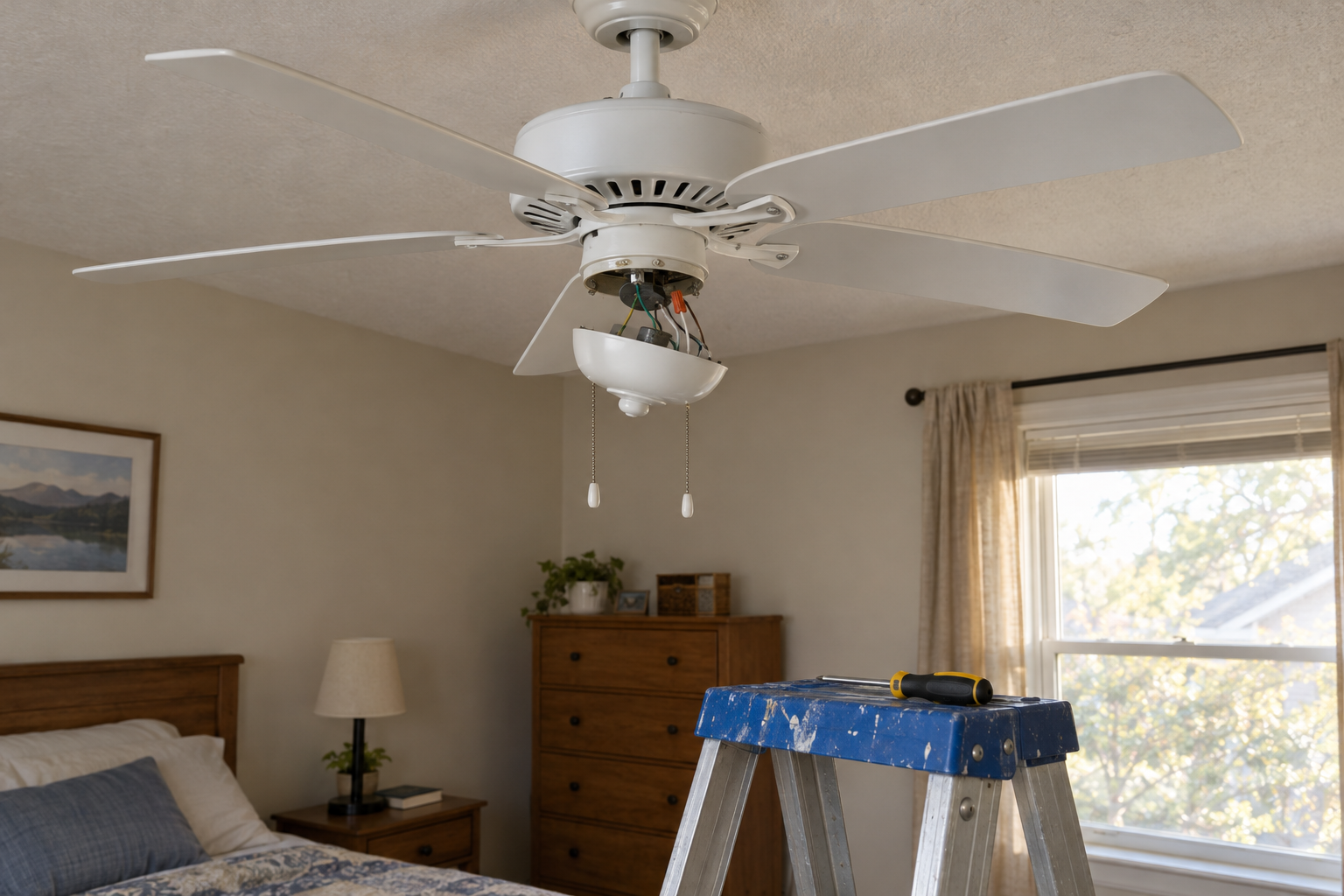
Three switches on one light means two 3-way switches on the ends and one 4-way switch in the middle, linked by 3-conductor cable so the travelers pass through every box. Get the hot onto the first common, the switched hot off the last common, and the travelers paired correctly at the 4-way, and the light will work from all three spots.
Quick steps: wire three switches to one light
- Turn off the breaker and prove the circuit is dead with a tester at every box.
- Label every wire in each box before you pull old switches.
- At the first 3-way, land the feed hot on the common (black screw) and the travelers on the brass screws.
- At the 4-way, land one cable’s travelers on one terminal pair and the other cable’s travelers on the other pair.
- At the last 3-way, land the travelers on brass and the wire to the light on the common.
- Splice all whites through to the light and pigtail every ground to its switch.
- Fold the wires in, mount the switches, restore power and test all three locations.
Tools and materials
- Two 3-way switches, 15 A (Leviton 5603 or Eaton 1303 or similar)
- One 4-way switch, 15 A (Leviton 5604 or Eaton 1304 or similar)
- 14/3 NM-B cable for runs between switches (12/3 on a 20 A circuit)
- 14/2 NM-B cable from the last switch to the light (12/2 on 20 A)
- Non-contact voltage tester plus a multimeter
- Wire nuts, yellow (two or three 14 AWG) and red (four 14 AWG)
- Wire strippers, needle-nose pliers, #2 Phillips and flat screwdrivers
- Black electrical tape for re-identifying white wires
- Masking tape and a marker for labeling
- Single-gang boxes rated 20 cubic inches or larger for the 4-way location
- Cable staples, cable clamps and a drywall saw if running new cable
Calculators for this job
Safety first
Turn off the breaker, then test every wire in every box with a non-contact tester and confirm with a multimeter set to AC volts. Three-switch circuits sometimes share a box with a second circuit, so test wires you are not planning to touch too.
How the three-switch circuit works
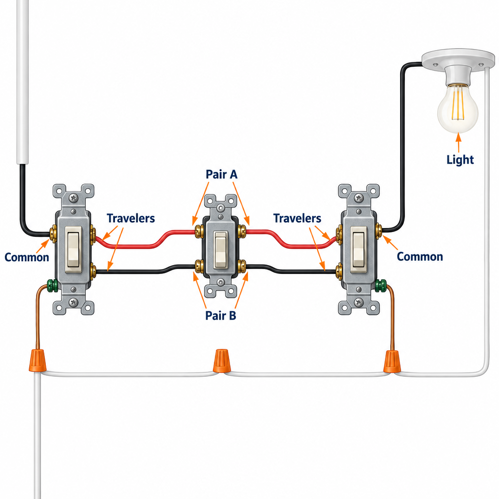
The travelers are the key. A 3-way switch has one common screw (black or dark) and two traveler screws (brass). Flipping it connects the common to one traveler or the other.
A 4-way switch sits between the two 3-ways. It has four traveler screws, grouped in two pairs, and it either passes the travelers straight through or swaps them. That swap is what lets the middle switch change the light’s state no matter what the end switches are doing.
Current path on a working circuit: breaker hot, first 3-way common, one traveler, through the 4-way, one traveler, last 3-way common, then to the light. Any switch can open or close that path.
You cannot use three 3-way switches, and you cannot use a regular single-pole switch in the middle. A 4-way is the only device that does the crossover. For four or more locations you add more 4-ways to the middle of the chain; the ends stay 3-ways.
Which cable goes where
Most houses are wired with the power feed arriving at the first switch, which is the cleanest layout and the one that keeps a neutral in every switch box. Here is what each run carries.
| Run | Cable | Black | Red | White |
|---|---|---|---|---|
| Panel to switch 1 | 14/2 | Hot feed | none | Neutral |
| Switch 1 to 4-way | 14/3 | Traveler | Traveler | Neutral pass-through |
| 4-way to switch 3 | 14/3 | Traveler | Traveler | Neutral pass-through |
| Switch 3 to light | 14/2 | Switched hot | none | Neutral |
Two other layouts show up in older homes. With the feed at the light box, the switches are dead-ended on 14/3 and the white wire is re-identified with black tape because it carries a hot. With the feed at the 4-way box, the whites in the two 14/3 cables carry the hot out to one end and the switched hot back from the other.
Both of those work electrically, but neither leaves a neutral in the end boxes. NEC 404.2(C) has required a neutral at switch locations since the 2011 code cycle, with limited exceptions, mainly so smart switches and occupancy sensors can be installed later. For new work, bring the feed to the first switch.
The rest of this guide follows the feed-at-switch-1 layout. If you are replacing switches on an existing circuit, the labeling step below matters more than the layout, because the labels tell you exactly where each wire goes back.
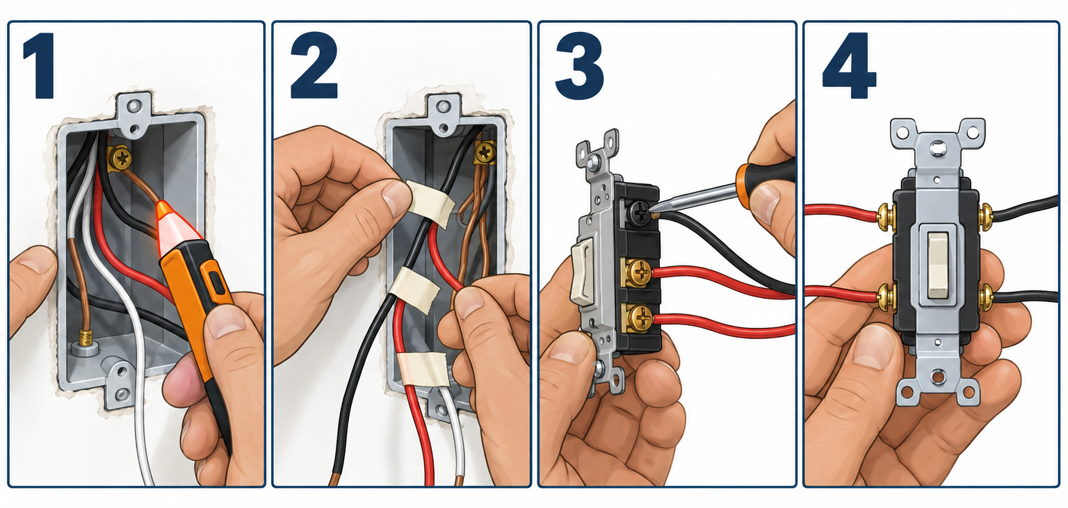
Step 1: Kill the power and confirm it
Find the breaker for the light. Flip it, then go to the light fixture and every switch box with your non-contact tester before touching anything.
Pull the cover plate, hold the tester against each wire and each screw. Then back the switch out of the box by its mounting screws, without disconnecting wires, and test the terminals directly with the multimeter. You want 0 volts between every wire and ground.
If any wire still reads 120 V, another circuit passes through that box. Find and turn off that breaker too. Tape the breaker handles so nobody resets them while you are in the walls.
Daylight helps here, since you will be working in the dark otherwise. A headlamp is worth having on this job.
Step 2: Label every wire before you disconnect anything
On an existing circuit, this step saves the job. Wrap a piece of masking tape around each wire and write where it lands: C for common, T1 and T2 for travelers, and at the 4-way, A1/A2 for one pair and B1/B2 for the other.
Identify the common on an old 3-way by the screw color. The common is black or a darker copper shade, and often sits alone on one side or at one end. The two brass screws are the travelers. If the switch has been painted over or the screws are all the same color, look for the word COMMON stamped next to one terminal.
On a 4-way, the pairs are usually marked by color, such as two brass and two black screws, or stamped IN and OUT. The two wires from one cable go to one pair. Label them as a pair before you pull them.
Take a phone photo of each box with the labels visible. Then disconnect the switches.
Pro tip
If the old switch is dead and you cannot tell which screw was the common, set the multimeter to continuity, hold one probe on the suspect screw and touch the others while you flip the toggle. The common screw beeps to one traveler in each position. A traveler screw only beeps in one position.
Step 3: Wire the first 3-way switch
This box has the 14/2 feed from the panel and the 14/3 cable heading to the 4-way. You should see two blacks, one red, two whites and two bare grounds.
Strip each conductor about 5/8 inch, or match the strip gauge molded into the back of the switch. Bend a clockwise hook in the end with needle-nose pliers so tightening the screw closes the loop rather than pushing it open.
Make the connections:
- Black from the feed cable to the common screw (black).
- Black from the 14/3 to one brass traveler screw.
- Red from the 14/3 to the other brass traveler screw.
- The two whites together under a yellow wire nut. The switch does not need a neutral.
- Both bare grounds and a 6-inch bare pigtail under a wire nut, pigtail to the green ground screw. Add a second pigtail to the box if the box is metal.
Tighten terminal screws to the torque on the device packaging. Most 15 A switches list 12 to 14 inch-pounds, which is firmly snug with a hand screwdriver and no extra grunting. NEC 110.14(D) requires following the listed torque, so a small torque screwdriver is a reasonable buy at around $30 if you do much of this.
Skip the push-in backstab holes on the back of cheaper switches. Use the side screws or the clamp-type back-wire terminals found on spec-grade devices. Backstabs loosen over time and are a common cause of flickering lights.
It does not matter which traveler goes to which brass screw. Only the common has to be right.
Step 4: Wire the 4-way switch in the middle
The middle box has two 14/3 cables and nothing else: two blacks, two reds, two whites, two grounds. Nothing connects to the light directly, so there is no “load” wire here.
Flip the 4-way over and read the terminal grouping. Leviton and Eaton 4-ways group the screws as two pairs, usually brass and black, sometimes labeled IN and OUT. The rule is simple: both travelers from one cable land on one pair, and both travelers from the other cable land on the other pair.
- Red and black from the cable to switch 1 go to the brass pair.
- Red and black from the cable to switch 3 go to the black pair.
- The two whites together under a wire nut, carrying the neutral through.
- Grounds together with a pigtail to the green screw.
Within a pair, red and black can swap and the circuit still works. What breaks the circuit is landing one cable’s red on the brass pair and its black on the black pair. That crossover is the single most common mistake on this job, and the symptom is a light that works from two switches and not the third.
Box fill matters in this location. Six insulated 14 AWG conductors count 2.0 cubic inches each, the grounds together count 2.0, and the device counts 4.0, for 18.0 cubic inches minimum. An 18 cubic inch box is at the limit; a 20.3 or 22.5 cubic inch box leaves room to fold everything in without crushing the splices.
Pro tip
Keep the 4-way’s two cables on opposite sides of the box as you fold them in, left cable to the left pair, right cable to the right pair. It makes the pairing obvious to the next person, and to you in five years when a traveler comes loose.
Step 5: Wire the last 3-way switch
This box has the 14/3 from the 4-way and the 14/2 going out to the light. You see two blacks, one red, two whites and two grounds.
- Red from the 14/3 to one brass traveler screw.
- Black from the 14/3 to the other brass traveler screw.
- Black from the 14/2 (to the light) to the common screw.
- Whites together under a wire nut.
- Grounds together, pigtail to the green screw.
The black on the common is the switched hot. It only carries power when the switch positions line up, which is why a non-contact tester at the fixture can read dead with the breaker on. Always test at the panel side too before trusting a dead reading at the light.
Step 6: Connect the light
At the fixture box, the 14/2 from switch 3 gives you one black, one white and a ground. Black to the fixture’s black or brass lead, white to the fixture’s white or silver lead, ground to the fixture’s green lead and to the box if it is metal.
To control more than one light from the same three switches, run 14/2 from this fixture box to the next one. Splice black to black, white to white and ground to ground, with a pigtail from each splice to the fixture leads. Every light downstream follows the switches together.
A ceiling fan with a light kit works the same way if you want wall control of the light only. Run the switched hot to the light lead and feed the fan motor from a separate switch or the pull chain, otherwise the fan drops out every time someone kills the light.
Step 7: Mount the switches and test
Fold the wires into the box in an accordion pattern, pushing the splices to the back first and the switch in last. Mount each switch with the toggle pointing the right way; on a 3-way or 4-way there is no fixed ON and OFF, so just keep them vertical.
Turn the breaker on. Test in this order:
- Flip switch 1. Light should toggle.
- Flip switch 2 (the 4-way). Light should toggle.
- Flip switch 3. Light should toggle.
- Repeat each one from the new state. Every flip of every switch should change the light, regardless of where the others sit.
If every switch changes the light every time, you are done. If any switch only works some of the time, go straight to the troubleshooting table.
Expect a 3-way switch to cost $2.50 to $18 and a 4-way $10 to $25 at a home center, depending on whether you pick a basic toggle or a premium rocker. If you are running new cable, 14/3 NM-B by the cut length runs roughly $0.72 per foot at specialty suppliers and $1.17 to $1.56 per foot at big-box stores for 50 to 100 foot cuts, so a 40-foot pair of runs lands around $60 to $125 in wire.
Running new cable for a third switch location
Adding a third switch to an existing two-switch circuit means opening the chain and inserting a 4-way. The existing 14/3 between the two 3-ways has to be rerouted through the new box, or replaced with two new 14/3 runs. You cannot tap a 4-way onto the side of the existing cable; both travelers must physically pass through it.
The practical approach in a finished house: cut in an old-work box at the new location, pull the existing 14/3 out of one 3-way box, and fish it into the new box. Then fish a new 14/3 from the new box back to the 3-way you just emptied. Use a fiberglass fish rod through the stud bays and a flex bit if you need to drill a top plate from the attic.
Secure cable within 12 inches of each box and every 4.5 feet along framing. Leave at least 6 inches of free conductor in each box beyond the cable clamp.
Most jurisdictions treat replacing switches as maintenance with no permit, while adding a new box and cable run usually requires an electrical permit and an inspection. Check with your building department before you cut drywall. In some states and cities, homeowner electrical work is not permitted at all on occupied dwellings.
Dimmers and smart switches on a three-switch circuit
A standard dimmer goes in one 3-way location only. Buy a 3-way rated dimmer such as the Lutron Diva DVCL-153P, wire it in place of one 3-way with the same common and traveler assignments, and leave the 4-way and other 3-way as ordinary switches. Two dimmers on one circuit will fight each other.
Smart switches change the game. The Lutron Caséta system uses one smart switch at any one location and replaces the other two switches with Pico remotes, which are battery-powered and mount in the existing boxes with a blank adapter. The travelers get capped off. A Caséta dimmer runs around $30 as a standalone unit and each Pico about $15 to $20.
Most other smart switch brands, including Leviton Decora Smart and TP-Link Kasa 3-way kits, need a neutral in the box and matching companion switches at the other locations. This is where the feed-at-switch-1 layout pays off, because the neutral is already there. A dead-end layout with re-identified whites will need a new cable run first.
Troubleshooting
| Symptom | Likely cause | Fix |
|---|---|---|
| Light works from two switches but not the 4-way, or only when another switch is in one position | Travelers crossed at the 4-way (one cable split across both pairs) | Move the travelers so each cable’s red and black share a pair |
| Light only works when one 3-way is in a specific position | Traveler landed on a common screw at one 3-way | Swap the wire on the common with one of the travelers at that switch |
| Light never comes on, no voltage at fixture in any switch combination | Hot feed not on the common at switch 1, or open neutral | Verify 120 V on switch 1 common with breaker on; check white splices |
| Breaker trips the moment you flip a switch | Hot shorted to ground or neutral, often a bare strand touching a terminal | Kill power, inspect each box for stray strands and nicked insulation |
| Light flickers or buzzes when a switch moves | Loose terminal or a backstabbed connection | Re-terminate on the side screws and torque to spec |
| Light works but one switch feels loose or hot | Undersized box crushing wires, or a cracked switch body | Replace the switch and upgrade the box if fill is over the limit |
| Switches work until someone turns on another light in the room | Shared neutral from a different circuit miswired into this box | Stop and call an electrician; multiwire branch circuits need proper handle ties |
To isolate a bad switch, kill the power and use the continuity test from Step 2 on each device in turn. A 3-way should connect common to one traveler in each position and never both. A 4-way should connect each A terminal to one B terminal, and the pairing should swap when you flip it.
If the switches test fine and the labels check out, the problem is almost always a cable swapped between boxes, meaning the 14/3 you think goes to the 4-way actually goes somewhere else. Pull the switches at both ends and tone out the cable with the continuity tester by shorting red to black at one end and checking for continuity at the other.
When to call a pro
Stop and call a licensed electrician if any box shows voltage after the breaker is off, if you find aluminum branch wiring (dull silver conductors stamped AL on the jacket), if the boxes are cloth-covered cable with no ground, or if the circuit shares a neutral with another breaker. Fishing cable through plaster or exterior walls, and anything that needs a permit in a jurisdiction that bars homeowner electrical work, is also electrician territory. Expect $210 to $750 or more to swap three switches, at roughly $70 to $250 per switch for labor and parts, and $400 to $900 to add a new switch location with cable.
FAQ
Do I really need a 4-way switch for three locations?
Yes. Two 3-ways handle two locations. Every additional location in the middle of the chain needs a 4-way, because only a 4-way can cross the travelers over. A single-pole switch in the middle would cut one traveler and leave the light working from only some combinations.
Does the order of the switches on the wall matter?
Electrically the 4-way has to sit between the two 3-ways in the cable chain. Physically, the three switches can be anywhere in the house. The cable routing decides which device goes in which box, not the room layout.
Can I use 14/2 cable between the switches?
No. The two runs between switches each need two travelers plus a neutral, so they must be 14/3 (black, red, white, ground) on a 15 A circuit or 12/3 on 20 A. Only the feed from the panel and the run from the last switch to the light can be 2-conductor cable.
How do I add a fourth switch later?
Insert another 4-way between the existing 4-way and either 3-way, using two 14/3 runs through the new box. The ends of the chain stay 3-ways no matter how many 4-ways you add. The same logic covers basic “3 way switch wiring” with two locations; every extra location just adds one 4-way.
Why does the white wire in my switch box have black tape on it?
Someone re-identified it because it carries a hot, usually in a feed-at-light layout where the switches are dead-ended on 14/3. That is legal and correct under NEC 200.7(C), but it means there is no neutral in that box. If you install a smart switch, it will likely need a new cable.
Which switch gets the dimmer?
Either 3-way at the ends, never the 4-way. Use a dimmer listed for 3-way use and install only one on the circuit. The other two locations stay as plain switches and simply toggle the light at whatever brightness the dimmer is set to.